Bluetooth is a great wireless technology that can cover a lot of applications. One of the most important things to consider with Bluetooth is the wireless range. The range of a Bluetooth or BLE system depends on a variety of factors, from the chip, to the antenna. The technology itself creates limitations given the modulation used. To understand Bluetooth range, we've sumamrized some of the most important Bluetooth ranges for Bluetooth Classic as well as various flavors of BLE:
| Bluetooth Classic (v2.1 and v3.0) |
Bluetooth LE (v4.2) |
Bluetooth 5 LE 2Mbps |
Bluetooth 5 LE Long Range |
|
|---|---|---|---|---|
| Range | Up to 100m | Up to 100m | Up to 50m | Up to 400m |
| Range (Free Space) | Up to 100m | Up to 100m | Up to 50m | Up to 400m |
The range above is an estimate, but free space range is close to an upper limit. This is the range without obstructions and without interference. Indoor range will be less because of both signal attentuation from walls and objects, as well as multi-path effects (constructive and destructive interference from signals coming at different angles).
Getting the most range out of a Bluetooth LE radio is usually a multi-step process that starts at the design phase. There are quite a few factors involved in getting the best range and we’re going to cover the most critical aspects that you should do. Aside from BLE, these approaches are valid beyond just Bluetooth but apply to Wi-Fi and other radios.
Now let’s get started by looking at everything that impacts BLE range, starting with the BLE Modulation.
The range performance of Bluetooth LE (and any wireless radio) depends on the modulation used. Higher datarates and modulations require higher signal levels, which means shorter ranges. With Bluetooth LE, there are several options for modulation that can be used and have an impact on range:
With Long Range PHY options, it's possible to get much more range in BLE, but it requires both radios to include support for the feature, which is still not common. For example, Smartphones do not currently support the Coded PHY features. Also, it reduces the data rate significantly. They are a great options for sensors and other devices that don't need to send a lot of information or that can tolerate latency.
Long Range PHY also have another downside: higher power consumption. Since the data is sent more slowly, the same amount of data requires more on-the-air time, which means the radio is in transmit mode longer.
 It should come as no surprise that the BLE range limit is ultimately limited by the Bluetooth LE chipset. Regardless of the rest of the design, the chipset sets the upper bound for performance, and the job of the rest of the circuit is to make sure the radio transmits and receives the signal with as little loss as possible.
To understand how to choose the BLE chipset with the best performance, there are two main parameters we need to consider: Transmit Power and Receive Sensitivity.
There are of course other parameters, but these are useful in more specific scenarios and if these are good, they indicate a well designed radio. Let’s review what Sensitivity and Output Power parameters are and what impact they have.
The BLE output power is the amount of power generated and transmitted by the BLE chipset. Assuming an identical antenna and circuit, a radio with a higher output power will have longer range because the Bluetooth receiver on the other end will see a higher signal level. This also means that this radio can move further away and provide the same signal level as a device with lower output power.
The transmit power of BLE radios are usually given in units of dBm which is a logarithmic scale using 1mW as reference, so 0 dBm is 1 mW, 3 dBm is 3 dB higher than 0 dB and means the 3dBm signal is almost 2x as high as 0 dB. Note that dB can be used with dBm regardless of units because dB is unitless. Below are a few reference levels:
| Power Level (dBm) | Power Level (mW) |
|---|---|
| 0 dBm | 1.000 mW |
| 1 dBm | 1.259 mW |
| 3 dBm | 1.995262 mW |
| 10 dBm | 10 mW |
| 20 dBm | 100 mW |
The transmit power of BLE radios available today usually range between 0 dBm to around 20 dBm, with the majority having an upper bound of 4 dBm or 5 dBm, but a few devices exceed this. As an example, Nordic's nRF52832 can output +4dBm, while the nRF52840 can output +8dBm.
The output power limit of a BLE chipset is mostly dictated by design and the capability of the chipset process as we’ll discuss in a minute. Note that increasing transmit power on a single device won’t automatically give you better range. Bluetooth is bidirectional, so the other device needs to be powerful as well to make sure packets are received at the longer range. A Good BLE Gateway with powerful sensors can have amazing coverage.
One downside of higher transmit output power is the that it comes at the cost of power consumption. The peak output current will increase significantly (remember that dB is an exponential, not linear measure). A full +20dBm device can reach peaks of 100mA or more. This isn’t practical in many BLE designs. Many of them run on coin cell batteries which have a nominal 400uA current rate and rely on capacitors to make up the difference for a short period of time. This is one of the design decisions every product developer has to make.
We mentioned that the power limit is related to the technology node used to make the BLE chip. CMOS is the class="anchor" name of technology used to create the silicon wafer and is practically what almost all chips are made of. While this technology is low cost (allowing for chips costing pennies), it works best for lower frequencies. Some specific CMOS nodes are better than others. At the high frequencies such as 2.4GHz used in Bluetooth and BLE Radios, CMOS becomes very inefficient, so that more power is needed to generate a higher output power.
When a BLE chip designer is designing the RF amplifier section, they have to make multiple decisions and tradeoffs, which leads to the results of the chips we design with.
Luckily, CMOS isn’t the only technology available. Silicon-Germanium or SiGe technology performs much better at higher frequencies, but is much more expensive compared to CMOS and used for high frequency RF devices, fiber optic and other high-speed niches. It's simply not useful in creating microcontrollers. You can take advantage of SiGe's performance by including an efficient power amplifier as an external chip at the output of your BLE device.
A power amplifier raises the output power and because of SiGe is much more efficient than the internal amplifier inside the BLE chipset. Practically all external BLE Power Amplifiers, such as those from SkyWorks, Qorvo and other vendors are made of SiGe since it’s popular for these applications.
There is a complication: remember that a BLE radio both transmits and receives. If there is a power amplifier in the way, it must not be in the RF signal path when the BLE radio is in receive mode or it will reduce the incoming signal. Power Amplifiers are meant for amplifying already large signals and are relatively noisy for the extremely very low incoming signals during receive mode.
So, the external BLE PA amplifier must be controlled to amplify the outgoing RF signal and shut down when receiving. This has to be done by the BLE radio, which complicates the BLE software and requires extra GPIO pins.
The receive sensitivity of a Bluetooth LE radio is the limit at which the radio receives packets reliably. If you’re listening to another person talk, the lower their volume becomes, the more difficult it becomes to understand them. Some words may be completely unintelligible.
BLE radios behave similarly. In order to get a number representing the lower limit, we have to define the limit at which we stop properly receiving data. This limit is defined as the Packet Error Rate which quite simply is the rate of packet errors (packets whose bits are wrong compared to what was actually sent).
When a wireless receiver receives a packet with low power it can have difficulty in properly decoding the packet because of noise. The higher the received power of a packet, the better, just like someone increasing their volume. But to compare radios, we need to have some criteria so we can compare them apples to apples.
In order to test wireless radios, standard packets are sent whose power level is controlled and lowered in many iterations to find a point at which the radio fails to successfully receive data at a decent rate.
For BLE, a standard Packet Error Rate (PER) of 30.8% with 1500 packets is used as the reference for measuring sensitivity. Meaning, a packet signal level which causes us to lose 30.8% of the packets will be defined as the limit of radio sensitivity. Your BLE radio will fail testing if your radio is worse than -70dBm. This number is the minimum specification required by the Bluetooth SIG (the organization that defines Bluetooth) but in reality, this rarely happens. This is an extremely high signal level in practice and BLE radios, even if they have some issues, will almost always pass. You shouldn’t rely on this as any indication that your radio is passing.
Note that Receive sensitivity is a negative number (which means a smaller and smaller signal level if converted to milliwatts). The more negative, the better. For example, -100 dBm receive sensitivity is 5dB better than -95dBm receive sensitivity. -90 dBm is 5 dB worse.
Properly designed BLE Radios with acceptable performance have a receive sensitivity of around -88dBm, but the very best BLE radio designs with the right radios can achieve around -96dBm to -97dBm which is 8dB better. This is a huge difference in performance and range, almost 3x the range theoretically, that is worth it.
Bad BLE designs can fall anywhere on this scale or fail completely, but you should strive for radios and designs that are above approx. -94dBm. Getting this performance starts with picking a good BLE radio that can achieve this level, then putting together the proper RF design, testing and tuning it. As we mentioned, picking a BLE chip capable of -95dBm and above is the first step.
The receive sensitivity limit of a BLE radio itself is, just like the transmit power, determined by the internal radio architecture and design and the technology it uses. Companies with significant R&D spending and experience usually have devices with better performance. The process node of the device matters a lot here (advanced nodes with better performance can cost more, hence more accessible to larger companies).
So now that we know about transmit power and sensitivity, we know that BLE chips set much of the limit of what’s achievable in terms of range. But there’s a lot more involved. Let’s look at what impacts range in the rest of the circuit, then we’ll look at how to improve things.
Remember that we mentioned that noise coupling to the radio worsens things? Yes, noise from the circuit will cause a loss of sensitivity, called “desense” in the wireless industry. Just as if suddenly a baby were to start crying while you’re talking to someone would make it hard to understand them. A major source of noise in BLE devices is the integrated DC/DC regulator which is actually part of the chip itself (the inductors are outside the package).
Most BLE devices need to regulate voltage to power the various internal circuits. Because of power considerations, a DC/DC regulator is used because it has the lowest loss (and highest efficiency) compared to a Linear Regulator (also called LDO). Because DC/DC regulators use high frequency switching to achieve voltage regulation, this switching (which is noisy) invariable ends up impacting the device performance.
So you have a choice in your design: Use the DC/DC regulator to achieve the lowest power, or disable it and use the integrated or an external LDO to achieve the best sensitivity (and therefore best range).
From empirical data and what we’ve observed, when running, the DC/DC regulator can cause a loss of 2dB in sensitivity (a desense of 2dB). This results in about 20% loss in range, in addition to anything else. How significant this is depends on your design and needs. If your design already has other issues, then 2dB adds to the problem, but for a good design achieving -94dBm with DC/DC is still good.
The DC/DC regulator isn’t the only source of noise. High current switching anywhere near a BLE radio chipset will impact sensitivity. One often ignored source of noise is the noise generated by BLE chipset GPIOs themselves.
If your design is using a high frequency SPI clock, for example, near a pin that’s close or connected to the radio, this noise can couple in. A very important design decision is to make sure to identify sensitive pins that when used will cause this. Because GPIO pins in many BLE chipsets are flexible, you can instead use them for low frequency work.
For example, we commonly put button and non-PWMed LEDs on pins that are close to the radio to avoid this issue. This issue is so significant that even BLE chipset vendors such as Nordic bring it up. Unfortunately, if it’s not taken into account during the design phase and properly tested, it can end up impacting the radio when it’s running and appear as random packet losses with no apparent reason.
Another common source of noise and interference can come from other transmitters in the design. These transmitters create harmonics (signals in frequencies that are multiples of the fundamental) that can often fall inside the 2.4GHz band and get received by the radio. Because the other transmitter is nearby, these signals are very strong and can overcome the desired signal that’s coming from very far and is very weak.
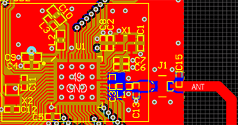
Assuming that interference is designed away from the BLE chipset or limited, the next important thing is to make the BLE RF circuit as best as we can, to make sure all the power reaches the antenna and the antenna propagates it properly. This is where proper RF circuit design comes in. RF design is both an art and science and much of it comes from experience. Because BLE radio chipsets are mostly integrated and have 50 Ohm output (which is almost ready to be fed to an antenna), there is not much to do except connect the radio to the antenna properly.
There are BLE radios that don’t have 50-ohm outputs, such as the older CC2540 and CC2541 from TI. This means that their output is differential and uses 2 pins and that a Balun is needed. The balun needs to be properly designed.
For BLE radios with 50-ohm outputs, it’s highly recommended to follow the manufacturer recommendations for external components. After this, it is critical to have a properly design 50-ohm line with an antenna and include any tuning components needed for the antenna. Imagine this: The BLE chipset is like a water source that outputs water using a 1-inch pipe. If you connect a 0.5-inch pipe, there will be some back pressure preventing the right water pressure at the output. Though this example is a bit limited, it should tell you that the RF circuit and impedance-controlled circuits should be well designed.
RF impedance-controlled traces require a careful attention to geometry and you need to properly control their width, height, the distance to the copper around them and the distance to the ground plane. This gets complicated when there are other devices on the board with their own requirements. For example, we once had to work on a design with several BGAs that required thin traces to connect the BGA balls, but this conflicted with the RF trace size. We had to re-design significant parts of the board to ensure every circuit got what it needed. There’s a lot to RF design, but a good RF design will help you get everything out of the BLE radio you chose.
The antenna as most people know is a critical part of the BLE performance, and no good radio can work well without a good antenna. Your antenna helps couple your circuit to the air, and the reality is that larger antennas are usually more efficient. By more efficient we meant that more energy gets properly coupled to the air.
Antenna design is an art in itself, and can require a few rounds of simulation testing and adjustment. Because this process is complex and costly many BLE designers adopt the antenna their vendor uses or well-known 2.4GHz which work well in many cases. But we’ve seen many cases where the antenna is not unsuitable, you may be sacrificing performance. Regardless of the antenna you choose, it’s critical to tune the antenna.
Every BLE design is unique, and the circuit itself often works as half of the antenna. An antenna that isn’t properly tuned can sacrifice many dB of performance. Tuning the antenna comes down to measuring the antenna in the most real-world scenario. For example, when a product will use plastic enclosure (which is most), then the antenna needs to be measured inside the plastic exactly as a user would use it.
Taking into account a user’s body and its impact on the product can also help. Ultimately all these elements affect the antenna and its ability to deliver the signal. Tuning will find the right design or component values that allow the antenna to transfer all the power in the 2.4GHz BLE bandwidth, which helps both receive and transmit.
Antennas are sensitive to many things, but it’s important to keep antenna way from Metal, dielectrics and noise. Anything near an antenna, especially closer than 8mm, will significantly impact its performance. If metal is near an antenna, it can cause the signal to couple to it instead of the air, as well as blocking the signals. Dielectrics or nearly any non-conductive material will cause some detuning of the antenna. Although not as bas as metal, it’s undesirable. It’s important to give an antenna space and a good location so it can do its job.
PCB antennas which are printed on a PCB are low cost but sensitive to the environment. But, they can be made quite large and customized allowing for some unique properties. Ceramic chip antennas are also very popular and allow smaller size solution. THey're typically less sensitive to detuning from plastics and other dielectrics.
We can't focus here on antenna selection because range is usually just part of the equation, but using external antenna or a custom antenna will provide you with the best performance. Especially one that is tuned and tested. To pick a good ceramic antenna, you will need to find one with good return loss. The more negative the return loss, the better. So an antenna with -10 dB return loss is much better than one with -5 dB return loss. We won't go into the calculations, but you should aim for a return loss of -10 dB or better.
When your BLE design is ready to test, one of the critical things to do is to test and tune the crystal using the loading capacitors. Some of this can be done digitally, if the tuning capacitors are internal to the chip. In other cases it has to be done by measuring and testing different capacitors.
The crystal in a BLE design creates the fundamental frequency used for transmission. The 26MHz, 32MHz or similar value crystal ends up multiplied many times to generate frequencies in the 2.4GHz band. As you can imagine, a small error in the crystal ends up affecting the signal. Most crystals are specified in Parts Per Million (ppm). Choosing a good crystal that is 20ppm or better helps give you a good and stable signal that can be well received.
A PCB circuit itself has some stray capacitance that shows up along with the crystal loading capacitors. This can lead to a few PPM in error, sometimes even beyond 20ppm. An error in the fundamental frequency can cause more errors. The impact depends on the amount of deviation, but that’s why you should test and make sure.
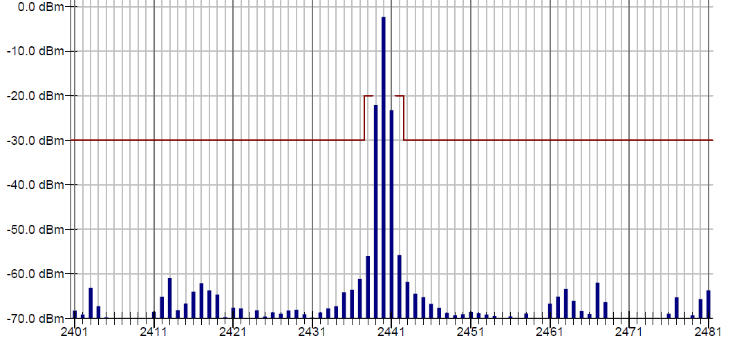
Custom BLE radios, where you physically put components on a PCB, have to be tested by a certified lab that creates a report used when you list your device with the Bluetooth SIG. At the lab, your device is connected to various instruments that test its performance. This is very useful in telling you if something is wrong (and that’s why the BT-SIG requires it). But often it’s the wrong approach: The lab is looking for you to meet some minimum requirements, not checking whether your device is as good as it should be. What’s worse is that by the time you submit the device for this testing you’ll be be far along the product development and even close to launch – there’s no time to change anything now.
We highly recommend that if you design a BLE radio to have it tested as soon as there’s a prototype. This testing should go beyond just the BLE pre-qualification testing. Harmonic testing, frequency accuracy, transmit power, sensitivity and other parameters can tell you very quickly whether your radio is good or whether you need to make changes and improvements. The earlier this is done the better and it also keeps costs low.
We’ve performed this service for many years and have managed to get radios with many issues back on track. It's pretty obvious when a BLE radio range is having issues, but it takes effort to find the root cause. Sometimes customers come to us late in the process, and the changes are significant and propagate down to other things. We hope you can do this as soon as your design is at a good state to be tested.
It's also important to get feedback and review BLE radio design during the design stage from engineers with knowledge in BLE and RF design. Doing this cuts down on the number of board re-spins and helps make sure your first prototype is successful.
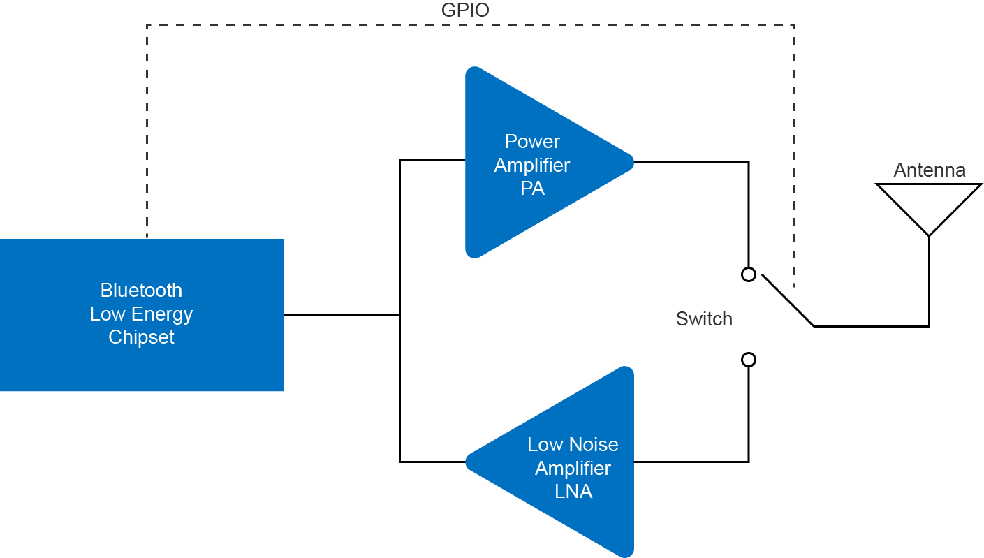
We’ve talked quite a bit about getting the most out of your BLE radio, and what to look at when choosing. We’ve talked about the BLE chipset being the limit for the output power and sensitivity. Most BLE chipsets have good sensitivity but not extreme output power. It’s possible to add a lot more power and maybe a bit or comparable sensitivity by using external devices. We mentioned them earlier, these are Power Amplifiers and Low Noise Amplifiers.
Power amplifiers take your signal and amplify them, allowing you to get higher transmit output power. Note that in practice your output power is limited by government regulations:
You should take into account that your devices should never exceed this, even due to device to device variation, temperature or other reasons. Sometimes calibration or slightly lowering the PA are needed to make sure the limit is never crossed.
Low Noise Amplifiers are amplifiers which themselves generate very little noise. This is useful as the first amplifier in an RF receiver – the lower the noise, the better you can receive your signal because the noise of an amplifier can overwhelm small signals. BLE RF signals coming in are extremely low, on the order of -90dBm to over -100dBm
Remember that PA and LNA need to be turned on/off depending on the state of the BLE radio. Because they usually work together and because size is a big concern, they’re usually integrated together in chips and modules called Front End Modules (FEMs). several vendors provide Front End Modules (FEMs) for 2.4GHz frequency bands and even specific ones for BLE.
Integrating a FEM can help your design go from a 0dBm output power to +13dBm or more and help with the sensitivity. With a PA or FEM your range can go over 1000m in open range. But this range comes at a cost: using with these devices adds to the development cost and effort and requires RF design experience. They also require additional space and add cost to the system.
Power consumption, a concern for most designs, means looking carefully at the FEM sleep current, not just the peak TX. Because most BLE products spend the majority of their time asleep, this parameter can dictate the total system current.
After designing with a BLE Front Module, you should perform the same set of pre-qualification BLE testing to ensure the whole radio chain working properly. We like to include power consumption measurements for multiple steps to give us a good idea of what to expect at every power level, and often we will reduce the power to a level that makes sense.
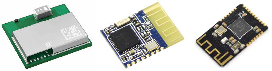
Our focus in this discussion has been on discrete designs, where you have complete design control. But for small volumes, many companies choose to use BLE Modules. Using a certified module has the advantage of being ready to go, but unfortunately many BLE modules don't have the best performance. Although most RF design of BLE modules is good, the small antenna and the fact that the module is tuned to a different board than your own design means that performance will be degraded. You can't tune the module. This is less of an issue for BLE modules with external antennas, but this increases the cost and takes up more space.

Mesh networking is another approach for increasing the range of devices by using a mesh network to help deliver data from one end to the gateway. Although BLE did not support Mesh Networking for a long time, the recent mesh capability announced for Bluetooth Low Energy promises to help give even better options.
Having a good radio can help your product, but there are cases where power consumption or obstacles can make increasing the output power to be ineffective. Mesh networking can help work around obstacles and create a reliable network while still keeping power consumption constrained. Obviously this means deploying more devices, which in some cases may already be needed for a network of sensors.
Getting the maximum BLE range is a complex task involving design decisions tradeoffs, testing, measurements and optimization. Understanding the practical aspects of each part of the process can help you make much better decisions and find out the best path for you to take to get the best range for your product and application. Some of the things you should do to get the most range out of your BLE design include:
Enter your email address to subscribe to this blog and receive notifications of new posts by email.