The MSP430 contains several families, from the low cost Value family to the most advanced F6xx family. Each family is usually targeted at a set of applications and contains a certain mix of peripherals. In a family, however, devices vary as far as the amount of Flash and RAM available. It is not unusual to develop using relatively large devices in a family, only to migrate down to reduce costs. Because of this, the tutorial will end up discussing several platforms, but will attempt to cover the lowest denominator first to make it accessible. The MSP430 Launchpad is the most accessible MSP430 platform and although the devices supported do not have all the peripherals of some of the mode advanced MSP430, it does cover so many peripherals that it makes it an ideal platform for starting.
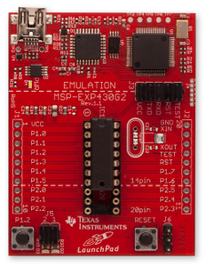
The MSP430 Launchpad is an easy way to get started with the MSP430. For a long time the board was sold at a promotional cost of $4.30, although it’s now available for $9.99. Still, the cost makes it difficult to say no. You can get one from TI’s Website.
The board contains a DIP socket capable of accepting most variants of the MSP430Gxx family. The most common device used is the MSP430G2553, which is a part running up to 16MHz with 16kB of flash and 512B of RAM. The USB connectivity on the board allows both programming with the on-board JTAG programmer, as well as UART communications for data transfer.
The board can be augmented with booster packs designed by TI and third parties that enable Wireless Communications, Wi-Fi, Batteries, Displays, and other elements. You can find booster packs here.
MSP430F5529 Launchpad
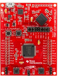
This MSP430F5529 Launchpad is one of the latest Launchpads. The F5529 along with the F55xx family integrate a USB Controller, opening the door to new applications and possibilities previously requiring a dedicated USB to UART converter. For a price of $12.99 you get an MSP430 that can go up to 25MHz, has 128kB of Flash and 8kB of RAM. With USB you can implement CDC, HID and MSC classes so you can be a serial port, a mouse or act as an SD card.
This board uses the same form factor as the classic MSP430 Launchpad, so booster boards can be reused.
MSP4305438 Experimenter Board
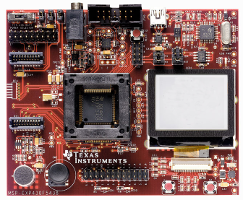
The MSP430F5438 and MSP430F5438A are quite popular devices due to the fact that they have 256kB of flash. Being some of the largest MSP430 devices makes them ideal for prototyping to support a wide range of applications. Some of the features of the board:
- 100 pin socket enabling quick insertion and removal of devices
- Dot-Matrix LCD with Backlight
- Audio Jack output with on-board Audio Amplifier
- 3-Axis Analog Accelerometer
- 5 position Joystick for navigation
- EM Connector headers supporting TI Low Power Transceiver Modules
The price of the board has recently increased due to lack of availability, but you can get it here.
EZ430-RF2500 Kit
Designed as a USB Stick, it is one of the most popular kits available from TI for those looking to try the MSP430 with a Wireless Transceiver. This inexpensive kit allows you to start using the CC2500 transceiver, a 2.4GHz radio that has become quite popular, especially given the kit’s $49 price.
One side of the stick contains the FET programming circuitry allow Spy-Bi-Wire communications with the MSP430 for debugging. The other contains the MSP430F2274 with the CC2500 and all circuitry needed for a connection. The MSP430F2274 is a relatively small device, 32kB of Flash and 1kB of RAM, so applications can be limited (especially by the RAM). Out of the box demo shows connecting the EZ430-RF2500 wirelessly to monitor temperature and voltage.
JTAG Programmer
Programming, Debugging and Flashing the MSP430 is done via the JTAG interface, or its pin reduced version called Spy-Bi-Wire. Although this JTAG is based on the IEEE 1149.1 Joint Test Action Group (JTAG) specification, TI has made modifications which mean that a MSP430 specific programmer must be used. The USB-FET is probably the most common programmer. A parallel port version was once available but has since become extinct given the disappearance of parallel ports and the emergence of USB.
The USB FET programmer is supported by practically all compilers and IDEs, including Code Composer Studio, IAR Workbench and Open source tools. The USB-FET programmer can be purchased from TI.
Physically the USB FET uses a 14 pin ribbon cable to connect to a target board, with two rows of 7 pins each. A small arrow indicates pin 1, and it is usually hard to connect it incorrectly on boards that have the shrouded header. The pinout of the significant pins is as follows:
| Pin | Name |
| 1 | TDO |
| 3 | TDI |
| 5 | TMS |
| 7 | TCK |
| 9 | GND |
| 11 | RST/NMI |
| 2 | VCC_FET |
All pins are required except for pin 2, VCC_FET. This pin provides a controllable voltage to the MSP430 if desired and if connected to the MSP430’s VCC pins. One must be careful about drawing too much current due to current limiting of the USB FET itself. 50mA is typically the maximum recommended current. It is typically best to power the MSP430 separately if possible to ensure clean voltage rails.
In Some cases, pin 2 and pin 4 are both required by certain third-party programmers to ensure target has proper voltage. Refer to the connection diagram for your programmer to ensure that all the signals are connected.
MSP430 Supporting Circuitry
Although the MSP430 Launchpad and Development boards contain everything that is needed to run an MSP430, it is important to know what external components are needed to ensure reliable operation. The MSP430 is relatively self-contained, but it still requires a few external components. The list below is general. For best performance, follow TI’s Hardware Tools Guide or reference design or contact us.
- Pull-up resistor of 47k with a on RST/NMI to ensure the MSP430 is not held in reset
- Decoupling capacitors on VCC, VCORE, and other pins located physically near the MSP430 for best performance. 0.1uF and decade values work best, but some applications require a filter network if transients are expected.
- JTAG connectivity as described in the JTAG Programming section, or Spy-Bi-Wire for devices without JTAG support
- MSP430 Core operates with 1.8V to 3.6V, but some modules may require 2.2V or 2.7V for proper operation
- Crystals as required for Timer/RTC/UART accuracy or USB operation
We will elaborate on some of these elements later, especially with respect to crystal selection and clock sourcing. In general, voltage requirements and crystal selection require careful consideration of the end application. MSP430 development platforms typically run at 3.6V, which makes them capable of running the MSP430 at the maximum frequency and support the operation of all modules. They typically also have footprints where 32kHz or high frequency crystals can be mounted.
*Photos courtesy of Texas Instruments