
We all want our Bluetooth Smart device to work the first time. But the reality is that it can take a lot of effort to get everything working smoothly. BLE products usually have a lot of moving parts that create a challenge, among them:
What makes BLE more challenging than other systems is that the drive towards low power means sacrificing some performance. The question is always whether the performance you’re getting is due to these tradeoffs or due to actual issues in the system. Like with all wireless links, packets are lost and you get interference from other devices, and a good product has to work even when this is the case.
Both Apple and Google make changes to their stacks, and when you add the difference in phone BLE chipsets, you can get some surprising results. Different phones with the same OS can sometimes behave very differently (especially the case with Android).
Because of all this, it’s important to have an arsenal of tools that can help you understand what’s going on in your system. We’re going to go over some of the critical tools and methods to debug Bluetooth Smart / BLE products.
The first thing we have to make sure is that the hardware is working properly. Deviations from the Bluetooth spec can mean an unstable connection or even failure to connect. If your design uses a BLE module such as one of Argenox’s BLE modules, then much of this is has already been taken care of. But, if you’re designing your own custom hardware there’s a few things that are common among all the chipsets. Below is a block diagram of a generic BLE system:
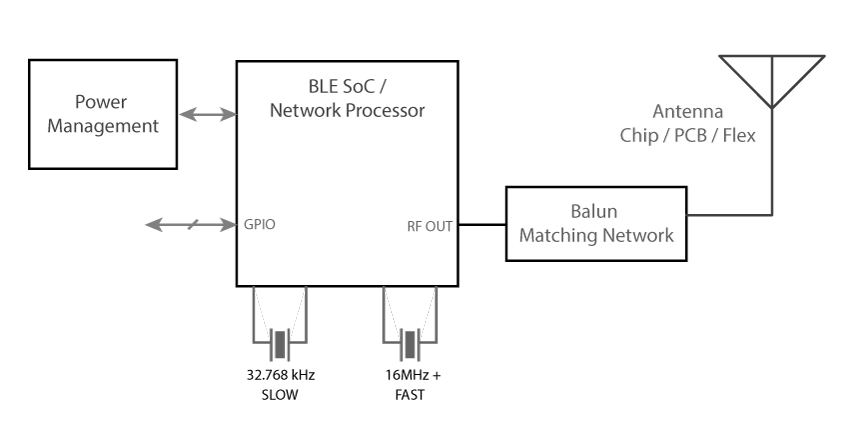
Bluetooth chipsets depend on two crystals, a fast one of 16MHz, 24MHz, 32MHz or similar frequency, and a low frequency crystal of 32.768 kHz. It’s critical for both of these crystals to be accurate, but there’s a tradeoff between accuracy, cost, and power consumption.
The high frequency crystal determines the carrier frequency and other parameters of the transmission. The more inaccurate, the more errors that are possible, so packet errors increase. This means higher power consumption and in some cases not being able to pass certification
Several BLE SOCs allow you to measure the output clock signal. Using a frequency counter you can accurately measure this. Note that it’s important to set the right loading capacitors (if needed) and to ensure the PCB is clean from contaminants (flux) that can change further it.
It’s possible to measure the offset by measuring the output BLE carrier signal when the BLE SoC is placed into a test mode (part of the BLE standard).
Several SoC devices allow calibration of the parts. In this case, it is possible to use cheaper crystals and calibrate during manufacturing.
The 32.768 kHz crystal is used for the Real Time Clock and for waking up during the right time window. Its accuracy is reported during connections because the master depends on it to ensure both devices wake up at the same time. If the 32.768 kHz crystal is inaccurate, it may wakeup at the wrong time, leading to packet loss and more transmissions. Note that this slow crystal is only needed in sleep mode. Products that don’t care about sleep can run off the high frequency crystal exclusively.
Some BLE SoCs include internal loading capacitors, but it’s more typical to find external loading capacitors. Selecting these capacitors depends on the crystal’s load capacitance, but sometimes PCB parasitic capacitance needs to be taken into account as well.
The Bluetooth stack needs to know the accuracy of the 32.768 kHz crystal and this should be specified correctly in the device configuration.
Different BLE chipsets have different requirements for power, but most devices operate in two modes:
The DC/DC configuration is more efficient, but generates significantly more noise. It’s possible to lose a couple dB of sensitivity from running using the DC/DC, so you’ll have to chose at the design stage what to use. Regardless of configuration, it’s important to ensure that the voltage rail to the BLE chip is good and free of noise which can also affect your sensitivity and performance.
It’s important to measure the voltage rail if you see any issues with your Bluetooth Smart system, especially if you notice less sensitivity in your circuit. Measuring the voltage noise can be done with an oscilloscope (preferable with a differential probe) and with the 20MHz bandwidth limit. Even if you don’t have a differential probe, use a spring loaded ground contact on your oscilloscope probe so that the loop area is smallest. It’s best to measure the noise coming out of your DC/DC regulator by measuring at the output capacitors, this is to eliminate noise that may be coming from other sources.
If you’re still suspicious that interference is causing problems, bypassing the DC/DC regulator and using a clean lab bench power supply can help eliminate a variable.
Another issue that can happen in Coin Cell battery designs is that the voltage dips when the system tries to draw significant current from the coin cell. Coin cell batteries have significant ESR (Equivalent Series Resistance) and are very limited in the peak current they can handle. If it’s too much, the voltage may dip below acceptable levels.
Finding this issue involves measuring the voltage at the battery or system terminals and forcing peak currents to happen (BLE transmissions, sensors running, processing, etc ).
The solution depends on the exact situation. it’s sometimes possible to shift the timing of sensors and processing to avoid the peaks, but sometimes capacitors are needed to provide the energy during the peaks. Be careful though because large capacitors can have significant (> 1uA) leakage current which can reduce the design lifetime.
Getting RF right is critical to ensure your system has the best range and performance. Bad RF design can result in low output power and low sensitivity which ends up affecting the range and the ability of the system to decode packets. Small design errors can accumulate and completely affect a solution, so a designer has to be very knowledgeable and measure the system to ensure it behaves as designed.
Although proper RF measurements are not covered here (they involve significant equipment and environment), there is a list of things to look for to discuss with your designer, manufacturer and during certification:
Solving RF issues late in the process can be expensive because you’ve already committed to the design. Your goal should be to have a good design early in the process that can be quickly certified.
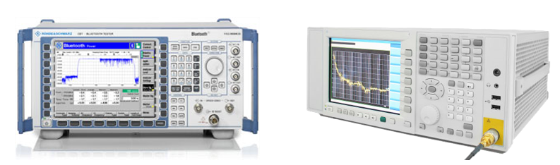
Investigating RF is best done RF chamber to avoid any outside interference, along with a Bluetooth Tester and other equipment to verify that the device is within spec. This may be followed by testing in an environmental chamber to ensure that no issues happen when exposed to higher or lower temperatures (which can affect the system).
Just because a device performs well in FCC tests doesn’t meant it will work well. This is because if a lot of power is lost before the antenna (due to an impedance mismatch), then it will pass certification but won’t work well in the field.
For quick time to market, consider using certified modules that have a proven design and have been certified. All the tests have already been performed for our Modules and custom modules we design for customers. Some other vendors perform them as well.
Testing the hardware can show a lot of issues, but it’s only a part of the puzzle. Ultimately hardware issues show up on the link layer with packet losses, disconnections, low throughput, etc.
If you’ve ever dealt with Bluetooth Classic (BR/EDR), you know that Bluetooth sniffers can be expensive, costing thousands of dollars. Capturing the fast Bluetooth packets and then decoding them requires quite a bit of processing, and the market was quite small (not many companies developed Bluetooth products, at least as compared to BLE today). Thankfully, in the case of BLE, it’s a lot simpler because of its GFSK modulation and the lower complexity of protocol. Vendors can provide a relatively simple sniffer that’s low cost and easy to use, and that should help you investigate most of the issues. Note that if you’re developing a Dual Mode system with both Bluetooth Low Energy and Classic, having a Classic sniffer is almost a must if you’re finding issues.
It’s important to understand the limitations of any wireless sniffer. Let’s say you’re sniffing packets between a BLE product and a phone. Then it’s possible that the sniffer sees packets correctly, but the phone may have seen the packets differently. After all, the phone has different circuity, is at a different location, and may have decoded the packet differently. So, it’s important to keep in mind that the sniffer is best used to see the process and data being exchanged, but that different devices may see packets differently. For example, the phone may be farther away and the signal too low to decode. Or the phone could be busy doing other things or scanning differently.
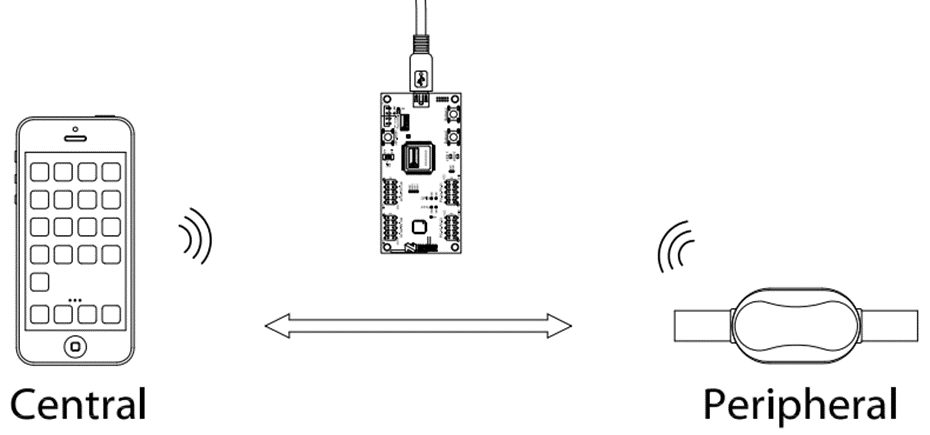
Image courtesy of Nordic Semiconductor
The Bluetooth LE sniffer shows you what’s over the air, but it won’t show you what’s happening inside of the devices. Often, devices may issue error codes which are not easy to understand or may be more complicated. In this case, it’s important to look at the device logs (more on this later).
BLE sniffers usually run in two modes:
Typically you will first look for the advertisements of the peripheral, then tell the sniffer to lock on to that device and sniff any packets by that device. You can then initiate the connection from the central device, transfer the data, all the while capturing what’s exchanged.
Obviously this approach has limitations. During connection mode, you can’t see advertisements that are being sent by other devices. In advertisement mode it’s possible for the sniffer to miss packets if the sniffer and the BLE device are not in complete sync. This can also be the case if the device changes the way it advertises.
Depending on the sniffer’s implementation, the sniffer usually locks on to a particular advertisement channel at a time and sniffs all packets sent. But, another device can be on a different channel advertising (most devices advertise on all 3 channels so this isn’t an issue).
Using a sniffer also requires that you have an understanding of the BLE protocol, what packets should be sent and when so you know when something is wrong, but we are going to cover a few of the big things to look at as well as a few of the available BLE sniffers are covered below.
You can get the nRF Sniffer from Nordic’s Website
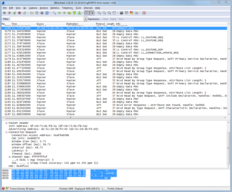
This sniffer uses a Nordic evaluation board with special firmware programmed to the device. The nRF51822 captures the BLE packets, adds time, RSSI, and other metadata, and forwards them to Wireshark. The advantage here is that Wireshark is an industry standard tool that allows anyone to view your information. Many engineers are familiar with its capabilities when sniffing TCP/IP and UDP packets.
We’ve found that we have to be careful with the version of Wireshark used. Sometimes there can be issues with newer versions of Wireshark misinterpreting the packets. For example, they indicate that they came from the Slave when in fact they were sent by the Master. Wireshark 1.10.14 seems to be the latest stable version and it is what you should use.
Using the BLE Sniffer is relatively simple once it is running, it opens a console window shown below:
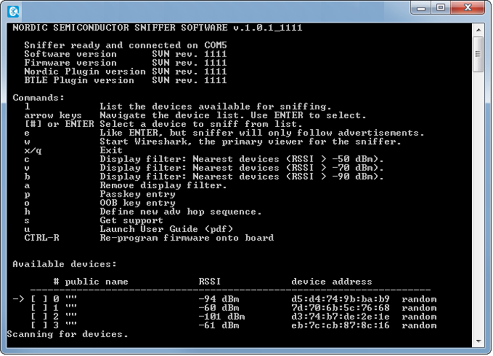
The software looks for a nRF51822 board with the firmware connected to the PC via USB. You can program the firmware using the nRFgo application. The console window will be updated with devices. You can press the number corresponding to the device you want to sniff. Then press W to open Wireshark which will show the live data in Wireshark. You should choose the peripheral device to which the central will connect (only peripherals advertise in BLE):
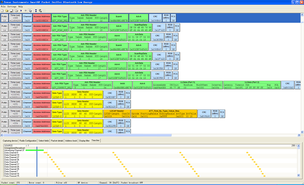
TI’s sniffer is a proprietary interface that captures packets similar to the Nordic sniffer. This software supports other protocols besides BLE, but we don’t need them. Just like Nordic’s sniffer, a USB stick with the right firmware is used. Currently only CC2540 USB Dongles or CC2540EM + SMartRF05EB boards can be used.
Either sniffer will do what you need, but it’s typically easiest to stick to a sniffer from the Bluetooth vendor you’re using, since it means you can use one set of tools. You probably already have an Eval board that’s ready to go.
Just in case you’re wondering, the sniffers will capture packets from other vendors. Nordic can be used to capture packets from TI devices and vice versa.
It’s not always necessary to get a sniffer. BlueZ is the open source Bluetooth Stack usually used with Linux and it also has sniffing capabilities, but they’re more complicated to use. With the right adapter, it’s possible to sniff packets and do a lot of things.
BlueZ is commonly available in Ubuntu and the lescan and hcidump tool together are valuable.
Although some BLE chipset vendors provide sniffers, teh real workshorses of the BLE sniffers are several commercial sniffers available. One major limitation of BLE sniffers are that they're limited to Bluetooth Low Energy, and that they're likely to miss important information. They can really only follow a single connection, which makes their usefulness limited when having to debug multiple connections and in many other scenarios
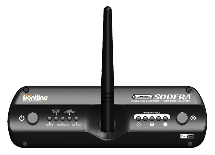
Frontline, which was acquired a few years ago by Teledyne Lectroy, has been in the business of selling wireless protocol sniffers for several years. Although they have many sniffers, the most relevenat ones are
The hardware in Frontline's offering is good, with the higher end units capturing the full bandwidth and decoding everything. They're also mobile units that can run from battery. These devices also provide features such as spectrum capture, which allows you to see whether packet errors are due to protocol issues or due to noise in the band. You can even augment the system with Wi-Fi capture for even more 2.4GHz data. This is useful in coexistence debug where Wi-Fi and Bluetooth are running together.
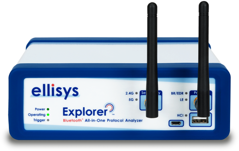
Ellisys offers the Bluetooth Explorer, which is another high end commercial sniffer. It can sniff BLE, BR/EDR (Bluetooth Classic) as well as Wi-Fi. It competes against Frontline's Sodera LE and Sodera devices
The hardware in Ellisys's offering is good, although perhaps not as sophisticated and future proof as Frontline. One place where Ellisys distinguishes itself is the sniffing software - we've used its sniffer and software in several projects and it's easy to follow the connection and data
We usually avoid using the vendor provided sniffers. For field work, we'll use the lower end BPA sniffer, or if needed use one of the higher end devices. The reality is that these sniffers are very low cost, but what you save in equipment you pay for in time. They can capture basic BLE packets, but you can see their limitations quickly when you're facing a more complicated problem that requires looking at multiple channels, packet errors due to noise, etc. They can't be used for capturing Bluetooth Classic BR/EDR for Audio applications. But the cost of these high end units make them commonly found only in few places such as R&D labs and companies like Argenox that specialize in Bluetooth debug and development.
Every application and issue is different, but there are a lot of common items you should look into when looking at how devices are behaving. These are some of the most common issues we look at when analyzing a product:
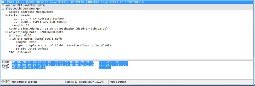
The first item of business when you’re looking at your device is to look at the advertising packets and their contents, as well as the spacing of the packets. The contents of the packets should be exactly as you set them in the firmware.
Below you can see the capture of an advertisement packet, along with the information provided. We’re showing the Nordic nRF Sniffer and Wireshark. If you open the Nordic BLE sniffer meta tree, you can see more details regarding the RSSI, channel and timestamp information, which can be useful.
If your connections fail to happen, the BLE peripheral may be sending packets too slowly, or their signal level may be too low. This can be an issue with output power, range between the devices, interference, or other issues.
There’s a lot happening when a BLE connection is established. The Master sends the slave a lot of parameters, among them the parameters for the connection.
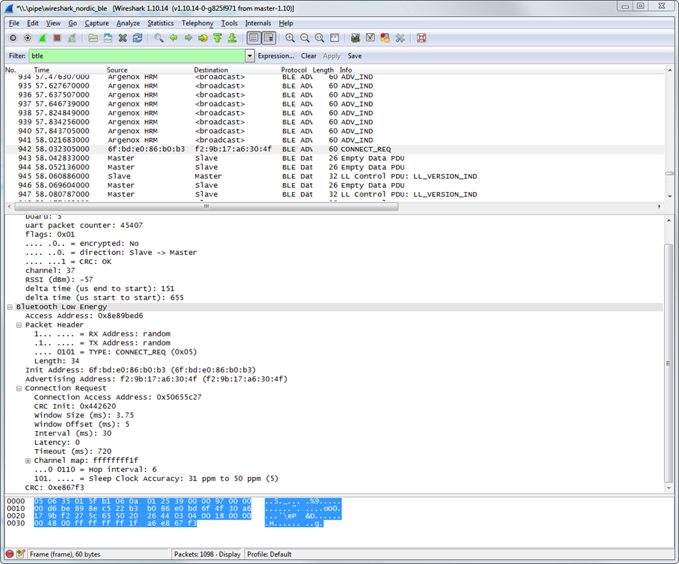
The BLE connection settings are some of the most critical parameters to understand in BLE. Connection interval, slave latency and other settings are sent upon during a connection, and they can tell you a lot about what the devices agree to. If you’re having connection problems, it can be that the two devices don’t agree on the parameters (and the central device disconnects).
In debugging any issues with the connection, it’s important to ensure that all the parameters are what they should be, that the CONNECT_REQ is acknowledged by the slave device, and that the connection process continues.
For example, an Android or iOS device that has to communicate with multiple devices may need to use a longer connection interval to be able to service all devices. This can cause all kind of issues from low throughput to disconnect. It’s easy to see when this happens if you capture the right packets.
Because BLE uses Adaptive Frequency Hopping (AFH), the channels used for communications can change during the connection. The central device constantly updates its channel table depending on the environment. How this is done is proprietary to each BLE chipset vendor, but usually relies on measuring packet loss, RSSI levels or a combination of both.
One of the first things we do when a customer sends us a capture or a device to analyze is to look at the environment. A lot of interference can be a problem and can explain lost packets, disconnections, low throughput, etc. Although you can use a spectrum analyzer device that looks at the full 2.4GHz spectrum, looking at the channel map that the BLE link uses can give you a good idea about what the devices themselves see happening.
For example, we’ve had cases where the environment was so congested, a customer device could use only 2 channels and the connections would drop.
During the connection, look for the LL_CHANNEL_MAP packet to see which channels are being used out of the ones available. If a significant portion of the channels aren’t available, testing should be done in an RF chamber to ensure the issue is related only to interference.
BLE uses the SN and NESN fields to detect lost packets. You can tell whether a packet had been retransmitted by looking at the change in the serial. A packet is retransmitted until the NESN is different from the SN value. While both NESN and SN are the same, it means the same packet is being re-transmitted.
BLE throughput is determined by a few elements:
The connection interval depends on both devices in the connection. For example, Android allows up to 7.5ms, while iOS allows 30ms in practice with some exceptions. With a BLE sniffer you can see exactly how many packets are being sent in each connection interval, who is sending it, and how many bytes are being sent.
If your throughput is too low, you should be able to see why looking at the data exchange, the connection parameters the devices agree to, etc. It will also let you find who is at fault.
Although not always used in BLE products, security, along with paring and bonding are important to understand. A sniffer trace can show you the exchange during pairing, but as soon as encryption is turned on, the packet data is encrypted and won’t always be readily decoded.
Several sniffers support sniffing data even if encrypted. In the case of the Nordic BLE sniffer it supports:
Most BLE devices talk to a smartphone on the other end. Because of this, understanding what’s happening on the phone itself can be critical. One of the most useful techniques for checking what’s happening in the phone is to use the operating system’s own logging capabilities. Both iOS and Android include the ability to capture the data and the events. The developers of the Bluetooth stacks in both companies use this ability to find bugs in their own stacks, and you should use it too.
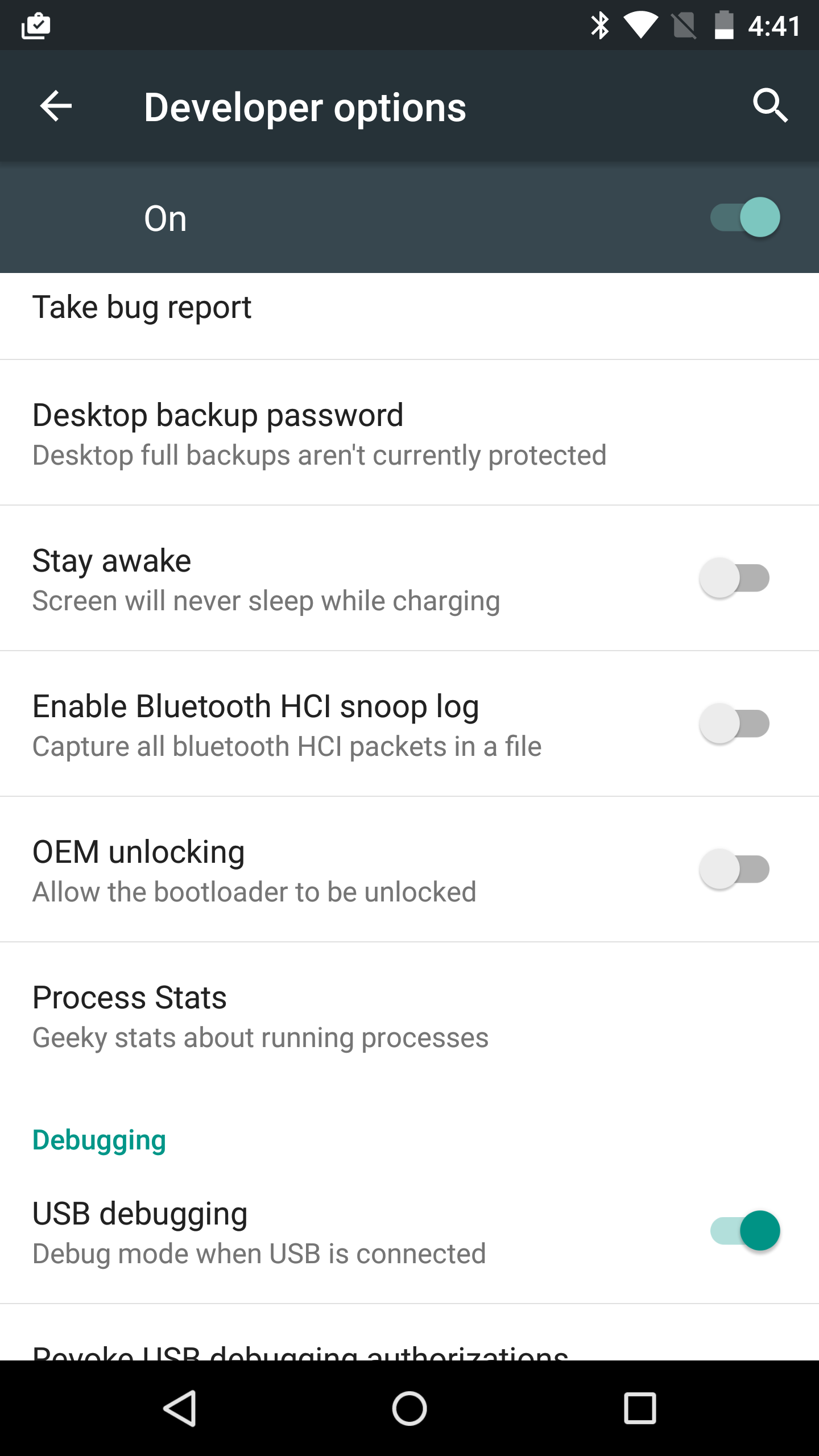
In Android, enabling the Bluetooth logging is as simple as going to Settings -> Developer Options and enabling “Enable Bluetooth HCI snoop log”. This will save the data in /sdcard/btsnoop_hci.log which can be copied and opened in Wireshark.
In iOS, enabling Bluetooth logging requires installing a special profile in the device. You can find more information on enabling it at https://developer.apple.com/bluetooth/
Once enabled, iTunes can sync the logs to a computer and they can be analyzed.
Most products use a BLE SoC chip in their design. In this case, a processor runs both the user application and the BLE stack. Examples of this are the nRF51822 from Nordic, TI’s CC2540/CC2541 and CC2640, Cypress PSoC 4 BLE, and many other parts.
Debugging the firmware can be more difficult than other embedded systems because the BLE stack needs to meet certain timing constraints. Simply putting breakpoints in the code can cause side-effects you won’t expect. For example, if you put a breakpoint in the code, the processor is halted and won’t run the critical BLE events, such as those to send a packet during a connection interval. The other device could end up assuming that the board being debugged disconnected (clearly not the case). So, when you use breakpoints in the code it’s very important to understand that changing the timing itself can affect the BLE connection. This is one of the most critical things to understand about using a debugger.
So if a debugger is very intrusive, what are the alternatives?
We have several approaches that are used in real-time embedded systems. All these approaches have tradeoffs. The right approach is to find something that is fast and provides the information you need to debug the issues.
This is a very simple and non-intrusive approach. Basically you set up a way to toggle a certain GPIO in your board when an event happens. Because changing the GPIO state is very quick (1us or less in most cases), the effect on the system timing is minimal.
The downside is that it’s difficult to get good insight into what’s happening in the system.
One approach we’ve used is to use multiple pulses to indicate different parts of the code that are getting executed, to understand how the system works.
Reading the pin is best done by attaching a logic analyzer to the GPIO, it’s possible to get a good idea of what the system is doing. Using an LED is similar but it is much slower and provides less information.
Printfs are common when debugging on computers. In embedded SoCs, the UART performs a similar function. But the problem is that most UART modules have no buffering capability. If you want to print the string “Function x() ran”, you need to send each character. This takes time. Worse is that many UART implementations are blocking, the processor manually sends each byte one by one and doesn’t do anything in the meantime. Interrupt implementation are much better.
With a standard baudrate of 115200, it can take several milliseconds to send the data across. This may or may not cause an issue.
We’ve seen cases where there were so many debug printfs that he stack slowed down and caused a lot of issues (disconnections, slowed down performance). Like any tool, use it judiciously.
Although sending human readable strings is easy to look at in a terminal, it’s very inefficient. Consider using a binary format that is faster, along with a simple interpreter running on the computer that allows you to quickly see what’s happening.
One downside of this method is that you either have to be able to use a UART or have a free one, but it’s better than other solutions because it doesn’t require any acknowledgment and is industry standard.
Another popular approach is to use a memory buffer to store events.
When running code, you can add an event to a fixed array. For example
Event_buffer[0] = 0x01; // Ran function x()
Event_buffer[1] = 0x05; // Ran function y()
When you are done running, you can view the buffer.
The advantage here is that this is very fast. Inserting data in the buffer takes a few CPU cycles, depending on the amount of data. But this can store the process through which the system is going.
Implementing this can be as simple as an array of numbers that show the state, but more likely it can be more complex. This complexity is a double edged sword which can provide tremendous amount of information or be complicated to implement.
| Debug Method | Advantages | Disadvantages | When to Use |
| Debugger | Ready to go. Gives an exact snapshot of the system, access to variables | System halts completely and affects the BLE protocols and communications | When you need complete understanding of variables |
| GPIO | Extremely fast and non-intrusive. Easy to implement | Only provides information that something happened. | To understand the order of code execution and what is getting executed |
| UART | No complicated equipment required | Requires a free UART module | |
| Event Buffering | Can be used to find extremely specific events. Extremely fast and non intrusive. Can hold very detailed information | Requires memory for capturing events. Can get erased if a reset occurs | Significant setup time |
Our recommendation for debugging is obviously to start with the debugger, since it provides significant information. The GPIO approach is probably the easiest and more useful. Such an approach can help detect restarts and all kind of conditions while performing system burn in.
The other approaches are useful when you need to dial down on a particular issue.
BLE stacks provided by manufacturers are usually closed source. This means that your visibility to what’s happening on the lower layers of the system is limited. You may be able to see the disassembly of the code, but not the original source code. User Guides and Manuals can only take you so far.
Despite what some vendors may tell you, their stacks can have bugs, but most vendors work hard to make improvements, especially if they affect a large number of customers.
If you’ve debugged the issue and you’re sure that it’s something in the stack, sample applications or other deliverable, first make sure that you’re running the latest stack version. For example, Nordic has made significant changes going from SDK 5.0 to SDK 7.0+ to SDK 8.0 and 9. Similarly, TI is constantly updating their stack for devices such as CC2640/CC2650. It will be hard to get support for an older stack since the vendor may have fixed it. Release Notes are useful to find out what has been fixed, and they often contain a list of known issues.
We’ve taken you through a lot of tools and approaches to debug your issues, but covering every eventuality isn’t possible. Sometimes you can still be stuck, especially in complex products with a lot of parts where BLE is only one of them.
All vendors provide forums to support their devices:
The forums can be great places to find information about an issue, but they can also be limited. Vendors support their own devices and it can be difficult to get an answer for selecting parts, development for other devices. In may cases solving particular issues also requires access to the particular hardware. Vendors want to sell their solution, so they’re less likely to point out other approaches that can be right for your product. They won’t dive deep to solve all the issues.
Because we provide unbiased and significant experience with product design, certification, we feel we can be a great resource in your development. Our customers certainly think so. With our experience and solutions, you can get your product to market faster, more reliable and with more features.
Feel free to send us an e-mail or contact us here,
Enter your email address to subscribe to this blog and receive notifications of new posts by email.