Although we are used to the base 10 decimal system for everyday counting, computers operate using a different system that uses only two digits, 1 and 0, to represent numbers. Counting in Binary, however, is quite unnatural for humans to use because even small numbers become long quickly. Using binary to represent numbers can be sometimes confusing but we will be using binary and hexadecimal values and operations extensively when programming the MSP430, so it’s critical to understand how they operate.
A CPU, and by extension a microcontroller, is a number cruncher. The first thing we must understand is how to represent numbers in a manner that the compiler, and therefore the CPU, can understand.
Because binary numbers tend to get long, hexadecimal is often used to represent the same values. Instead of base 2 as in binary, or base 10 as in decimal, hexadecimal uses base 16 which is still a power of 2. A compiler easily hexadecimal numbers, so using hexadecimal can make code more readable. The following table shows the relationship between decimal, binary and their equivalent representation in binary:
| Decimal | Binary | Hexadecimal |
| 0 | 0 | 0 |
| 1 | 1 | 1 |
| 2 | 10 | 2 |
| 3 | 11 | 3 |
| 4 | 100 | 4 |
| 5 | 101 | 5 |
| 6 | 110 | 6 |
| 7 | 111 | 7 |
| 8 | 1000 | 8 |
| 9 | 1001 | 9 |
| 10 | 1010 | A |
| 11 | 1011 | B |
| 12 | 1100 | C |
| 13 | 1101 | D |
| 14 | 1110 | E |
| 15 | 1111 | F |
The hexadecimal system uses the letters A through F for digits above 9. So with one hexadecimal digit we can represent 4 binary digits, also called a nibble. But, how is a compiler to understand whether 10 is a decimal number, a hexadecimal number or a binary number? In the C language, which we will be using extensively, a prefix is used. To represent a hexadecimal number, 0x is placed before the number. For example, if we wanted to represent F in hexadecimal we will write 0xF.
It’s important to note that leading zeroes don’t change the actual value represented. However, the presence of leading zeroes does indicate the total range available. For example, 0xF indicates a total of 4 bits, while 0x0F indicates that a total of 8 bits are available, but the upper 4 bits are 0. We will see that setting a register to 0x0F or 0xF has the same result.
If you look at the code we used for the first application, you will notice the line:
P1DIR |= 0x01;
0x01 is a hexadecimal number. We are setting bit 0 (the lowest bit) high.
One very common operation done in microcontrollers is setting and clearing of bits. For example, we might want to set the 3rd bit. In binary this is represented as 100, or 0x04 in hexadecimal. The following table shows the relationship between bits and locations and their hex values. You might notice that as we cycle through individual bit locations we go through powers of 2, namely: 1, 2 4 and 8 (note that we begin counting from 0):
| Bit Position | Binary | Hex Value |
| 0 | 00000001 | 0x01 |
| 1 | 00000010 | 0x02 |
| 2 | 00000100 | 0x04 |
| 3 | 00001000 | 0x08 |
| 4 | 00010000 | 0x10 |
| 5 | 00100000 | 0x20 |
| 6 | 01000000 | 0x40 |
| 7 | 10000000 | 0x80 |
We will use these values all the time when programming the MSP430
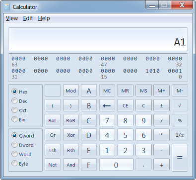
At times you’ll have to convert between the number systems for numbers like 0x5378 which are not easy to convert to decimal. Most operating systems provide a calculator capable of converting between decimal, binary, and hexadecimal. The windows calculator available in Windows XP and Windows 7 is one such application. Enter the calculator programmer mode and select the initial number system. For example, we want to know what the number 0xA1 is in decimal. So, select hexadecimal and type A1. Then click on the radio button called Dec to select the decimal number system.
Note that due to 2’s complement representation of numbers, one must be careful when dealing with numbers that are negative. In 2’s complement, the uppermost bit indicates whether the number is negative. Positive numbers are not a problem, but in the calculator you need to select the right number of digits as indicated by the Byte, Word, Dword and Qword options. Let’s assume we’re working with signed 8-bit numbers. Then the uppermost bit (bit 7 if counting from 0) indicates whether the number is negative or not. 10000000 is -128. Had you selected Word (16-bit representation), the decimal representation would have been 128 because calculator would have treated bit 15 as the sign bit. Bit 7 would have been treated as a positive weight.
The issue above with the sign brings up an interesting problem. Let’s say we have a sensor that is 12-bit, meaning that the 11th bit (the uppermost bit counting from 11) is the sign bit. When interpreted by most software that works with 8, 16 and 32 bit numbers, any 12-bit number will be interpreted as positive, when in fact it might not be. To solve this, a number needs to be sign-extended. Sign Extension preserves the value of the number, but moves the interpretation of the sign bit correctly. For example, we can sign extend a 12-bit number into 16-bits. Some processors such as the x86 come with a dedicated instruction to perform sign extension, but the MSP430 doesn’t have that capability. Performing a sign extension is quite simple. If the sign bit for the 12-bit number is set, all bits to the left of that bit (up to the uppermost bit 15) should be set to 1.
Let’s assume that we received a 10-bit value from a sensor 1111110001. Interpreting it as a 10-bit number shows this is the number -15. By setting all bits on the left of the leftmost one to one, we maintain the value. 1111111111110001 is the same number, just with all ones up to the last bit in 16-bit representation. Viewed in the Windows calculator in WORD mode you can see this number is still -15.
The C compiler requires a programmer to specify the data type to be used for every variable declared. These data types are processors specific, so it’s important to understand the size of data types available. Signed types refer to data types where the uppermost bit is treated as a sign bit and indicates whether the number is negative or not. Unsigned types treat that bit as any other bit, so the number is always positive.
| Data Type | Bits | Decimal Range | Hex Range |
| Unsigned Char | 8 bits | 0 to 255 | 0x00 to 0xFF |
| Signed Char | 8 bits | -128 to 127 | 0x00 to 0xFF |
| Signed Int | 16 bits | -32768 to 32767 | 0x0000 to 0xFFFF |
| Unsigned Int | 16 bits | -0 to 65535 | 0x0000 to 0xFFFF |
| Signed Long | 32 bits | -0 to (2^32)-1 | 0x00000000 to 0xFFFFFFFF |
| Unsigned Long | 32 bits | -2^31 to (2^31)-1 | 0x00000000 to 0xFFFFFFFF |
Choosing the right data type is critical to ensure operations such a addition, subtraction operate correctly since otherwise overflow will occur and results will be incorrect.
Representing numbers is useless with doing something on them. Along with arithmetic operations such as addition and subtraction, AND, OR, NOT and XOR are operations you will be frequently performing while controlling microcontrollers because bitwise operations are common. If you are not familiar with these operations, they are covered next. We will be using them in the next section.
| A | B | A OR B |
| 0 | 0 | 0 |
| 0 | 1 | 1 |
| 1 | 0 | 1 |
| 1 | 1 | 1 |
| A | B | A AND B |
| 0 | 0 | 0 |
| 0 | 1 | 0 |
| 1 | 0 | 0 |
| 1 | 1 | 1 |
| A | B | A XOR B |
| 0 | 0 | 0 |
| 0 | 1 | 1 |
| 1 | 0 | 1 |
| 1 | 1 | 0 |
| A | A NOT |
| 0 | 1 |
| 1 | 0 |
| 1 | 0 |
| 1 | 1 |
In the tables, A and B are one digit binary numbers with a value of either 0 or 1. The third column represents the value after performing the operation. OR, AND and XOR are binary operators because they require two operands (such as A and B). NOT is a unary operator because it requires only one operand (such as A).
You can think of OR as an operator of if either one is a ‘1’, the result is ‘1’. AND on the other hand requires both operands to be ‘1’ in order for the result to be ‘1’. XOR can be thought of as indicating difference. If A and B and different, then the result is ‘1’. Not is simply the opposite of the operand.
We now go to actually make use of the operations above. We will be performing bit operations in the C programming language on variables. Both variables A and B below will be considered unsigned char with 8-bits. We will explore some common operations that depend on bits.
Lets assume that the microcontroller has detected some event and we want to store it. One easy way of doing this is to create a variable and set it to 0 or 1.
char flag = 0;
flag = 1;
But, this can be wasteful. We are only really using 1 bit out of 8. To improve memory usage (which is always a concern in microcontrollers), we can use bit operations to set, clear and check individual bits, so we are using all 8 bits for various purposes. Lets look at the same operator bit wise:
flags = 0; // A flag for each bit
.
.
.
flag |= 0x01; // Some event happened
.
.
.
if(flag & 0x01)
{
    // Do something
    flag &= (~0x01); // Clear flag
}
The code above is something embedded programmers do all the time. Inside an interrupt routine or function, a bit is set. Notice the operator |= performs a bitwise assignment to the variable flags, in this case it ORs flags with 0x01. This is a convenient shorthand to writing:
flag = flag | 0x01;
You can visualize this with bits as follows:
0 0 0 0 0 0 0 0
OR
0 0 0 0 0 0 0 1
= ————————
0 0 0 0 0 0 0 1
The operations above are performed bit by bit on each position. The result is that the variable flag has bit 0 set with a ‘1’.
At a later time when we are processing events, we might want to know whether the event happened, so we use the AND operator, indicated by &. When we perform the AND operation with the value 0x01, the result will be 1 only if bit 1 is set (the event happened). Otherwise the AND operation will return 0 and the if statement will not execute the code in the curly braces.
0 0 0 0 0 0 0 1
AND
0 0 0 0 0 0 0 1
= ————————
0 0 0 0 0 0 0 1
And if the event never happened so flags is 0x00:
0 0 0 0 0 0 0 0
AND
0 0 0 0 0 0 0 1
= ————————
0 0 0 0 0 0 0 0
The if statement will run the code only if the result of the AND is 1 or greater (if any of the bits are set).
If the event happened, we must clear the flag so that we can know when a new event occurs. Again we use the AND for self-assignment by ANDing flag with the inverse of 0x01.
X X X X X X X 1
AND
1 1 1 1 1 1 1 0
= ————————
X X X X X X X 0
Notice that we used X for the uppermost bits. We did this because it’s important to note that the bit wise operation only affects in this case one bit. All the other bits are ANDed with ‘1’ and remain the same. This operation is also referred to as bit masking. Using AND and OR on bits allows us to set, unset, and check for the presence of any bit. This is important when configuring the MSP430 registers, which we will cover soon.
0x02 & 0x02 // Result is 0x02
0x02 & 0x01 // Result is 0 because bit 0 is not set
0x02 & 0x03 // Result is 0x02 because bit 1 is the only one set
0x02 & 0xFF // Result is 0x02 because ANDing with 0xFF has no effect
0x02 & 0xFF // Result is 0x02 because ANDing with 0xFF has no effect
0x02 | 0x02 // Result is 0x02 because bit 1 already set
0x02 | 0x01 // Result is 0x03
The XOR operator is also quite useful. As the different operator, it enables us to toggle bits.
0 0 0 0 0 0 0 1
XOR
0 0 0 0 0 0 0 1
= ————————
0 0 0 0 0 0 0 0
Notice that we performed an XOR of 0x01 with 0x01 and obtained 0x00. Bit 0 flipped. If we perform another XOR using 0x01:
0 0 0 0 0 0 0 0
XOR
0 0 0 0 0 0 0 1
= ————————
0 0 0 0 0 0 0 1
The bit has flipped again, despite the fact that we performed the exact same operation. XOR toggling comes in handy when we’re toggling a blinking LED and we want to change the state from ON to OFF and vice-versa. If we want to perform this operation in C, we can do as follows:
char flag = 0;
flag ^= 0x01; // Results in setting flag to 0x01
flag ^= 0x01; // Results in setting flag to 0x00
Note that again we are using the shorthand notation to set flag to the result of the XOR.
The C language allows us to define a preprocessor replacement using the #define command. This allows us to write more human readable values. The values below are defined in msp430.h, which is a header file included in Code Composer Studio:
#define BIT0 (0x0001)
#define BIT1 (0x0002)
#define BIT2 (0x0004)
#define BIT3 (0x0008)
#define BIT4 (0x0010)
#define BIT5 (0x0020)
#define BIT6 (0x0040)
#define BIT7 (0x0080)
#define BIT8 (0x0100)
#define BIT9 (0x0200)
#define BITA (0x0400)
#define BITB (0x0800)
#define BITC (0x1000)
#define BITD (0x2000)
#define BITE (0x4000)
#define BITF (0x8000)
With these definitions we can perform the same bit operations without having to remember the hexadecimal value for the position:
char flag = 0;
flag ^= BIT0; // Results in setting flag to 0x01
flag ^= BIT0; // Results in setting flag to 0x00
Before compilation, the preprocessor goes through all files and performs the preprocessor commands such as #include, #define, etc.
ASCII is a character encoding scheme. Glyphs such as letters and numbers are represented by an equivalent hex scheme, making it possible to encode strings in our application and communicate in a way that a human being can understand. The characters encoded include English characters, both uppercase and lowercase, as well as numbers, punctuation symbols and some control codes. Let’s see an example:
ch = 0x41;
The code above sets the variable ch to the hex value of 0x41. Code Composer Studio and terminal applications can interpret this in ASCII and will see the uppercase letter ‘A’. CCS also allows us to use ASCII directly, since it handles all the underlying representation values:
ch = 'A';
As you can see above, we can use single quotes to delineate single character value. When viewed in a memory editor, you will see 0x41 when seen as hex.
It’s very important to differentiate the single character ‘A’ from the NULL terminated string “A” which cannot be stored in a single 8-bit character.
Wikipedia contains a comprehensive ASCII Table.
Enter your email address to subscribe to this blog and receive notifications of new posts by email.