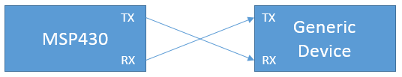
From a pinout perspective, UART signals only require one line for unidirectional communications, although two are typically used for bi-directional transmit and receive. Being asynchronous, UART signals don’t require any other clock line because the two UART devices agree on a common baud rate, stop, start and data bits. This makes the receiver capable of decoding the data. UART is connected by crossing the TX and RX lines, as shown below:
UART transmits bits sequentially by pulling the UART line low for a fixed amount of time determined by the baud rate. The UART line when idle is high at the I/O level, 3.3V or whatever the VCC of the MSP430 is set. RS232, on the other hand, uses similar signaling to UART but also incompatible voltage levels (the voltages are high and some are negative) that will damage the MSP430. Therefore, never connect an RS232 device directly to the MSP430. Use a MAX232 or similar device to convert between the two signal levels.
The smallest element of transmission is the UART frame or character, which consists of the Start bit/s, data bits, stop bits and optional parity bits, as shown below:
| Bit number | 1 | 2 | 3 | 4 | 5 | 6 | 7 | 8 | 9 | 10 | 11 |
| Start bit | Start bit | Data Bit | Data Bit | Data Bit | Data Bit | Data Bit | Data Bit | Data Bit | Data Bit | Stop Bit | Stop Bit |
The start bits alerts the receiver that data is coming. Without it, if the first bit was a ‘1’, it would be seen as an idle line since an idle UART line is also high. The number of data bits is typically 8, but it can be configured for 7 bits as well. Although some UART receivers can use a different number of bits, only 8 or 8 bits are supported by the MSP430. After the data bits stop bits are sent along with an optional parity bit.
MSP430 families contain different peripherals capable of UART communications. Among these are USCI, USART and eUSCI modules. UART can also be generated using timers or even bit-banged. Some peripherals have sophisticated options that we will not cover since they are rarely used.
We previously covered the issue of signal multiplexing. In order to use UART, specific pins that are connected to the UART module must be used, and the pin muxing must choose the Primary Peripheral mode. On the MSP430G2553 that is on the MSP430 Launchpad, UCA0 pins are present on pins P1.1 and P1.2 as UCA0RXD and UCA0TXD, respectively. Setting the pin muxing is simple since TI provides the information for the bit settings in the datasheet of the device. In this case, UART requires both PxSEL and PxSEL2 to be set to ‘1’. PxDIR does not need to be configured.
Configuring MSP430 Pin Muxing for UART
P1SEL |= (BIT1 | BIT2);
P1SEL2 |= (BIT1 | BIT2);
With the pins configured, we must configure the clocks for UART. The baudrate generation requires a clock of a certain precision. Although baudrates vary, 9600 and 115200 baud are the most common and we will focus on them. In order to generate a baud rate, we must feed a large enough clock so that it can be divided by the baud rate generator for the actual baud rate. For 9600 baud we can use both the slow 32.768kHz crystal if one is present, or a faster source such as the internal DCO or an external crystal. 115200 baud requires a fast clock, so only the DCO and a fast external clock can be used. Below we have the code needed to configure USCI_A0 for UART operation at 9600 baud:
Configuring MSP430 Pin Muxing for UART
#include <msp430.h>
int main(void)
{
WDTCTL = WDTPW + WDTHOLD; // Stop WDT
/* Use Calibration values for 1MHz Clock DCO*/
DCOCTL = 0;
BCSCTL1 = CALBC1_1MHZ;
DCOCTL = CALDCO_1MHZ;
/* Configure Pin Muxing P1.1 RXD and P1.2 TXD */
P1SEL = BIT1 | BIT2 ;
P1SEL2 = BIT1 | BIT2;
/* Place UCA0 in Reset to be configured */
UCA0CTL1 = UCSWRST;
/* Configure */
UCA0CTL1 |= UCSSEL_2; // SMCLK
UCA0BR0 = 104; // 1MHz 9600
UCA0BR1 = 0; // 1MHz 9600
UCA0MCTL = UCBRS0; // Modulation UCBRSx = 1
/* Take UCA0 out of reset */
UCA0CTL1 &= ~UCSWRST;
/* Enable USCI_A0 RX interrupt */
IE2 |= UCA0RXIE;
__bis_SR_register(LPM0_bits + GIE); // Enter LPM0, interrupts enabled
}
/* Echo back RXed character, confirm TX buffer is ready first */
#pragma vector=USCIAB0RX_VECTOR
__interrupt void USCI0RX_ISR(void)
{
while (!(IFG2&UCA0TXIFG)); // USCI_A0 TX buffer ready?
UCA0TXBUF = UCA0RXBUF; // TX -> RXed character
}
The clock source for the UART baud generator is SMCLK sourcing the DCO running at 1MHz. Before we can configure the UART peripheral we need to place it in reset mode. Not all registers require this but it is best to do so when first configuring USCI, whether it’s for UART or any other mode. Notice that we use the assignment operator, so all the other bits are set to zero. With the reset in place, we make SMCLK the clock source for the UART. Being flexible, there are other possible options for the UCSSELx:
UART can actually use a clock coming on a pin instead of one of the internally generated clocks. This can be useful in reducing the number of clocks in the system and reducing system cost.
Getting the baudrate from the clock and configuring the baudrate registers is often the most confused to those trying to use the UART capabilities of the MSP430. Obtaining the main divisor is often easy, but adjusting modulation and other bits can be tricky since they need careful adjustment to reduce error. TI provides a list of register values for common clock frequencies that makes baud rate configuration easier.
| Clock | Baudrate | UCBRx | UCBRSx | UCBRFx | UCOS16 |
| 1,048,576 Hz | 9600 | 109 | 2 | 0 | 0 |
| 8MHz | 115200 | 69 | 4 | 0 | 1 |
| 16MHz | 115200 | 8 | 0 | 11 | 1 |
The two clocks selected represented some of the lowest error rates, as reported by TI. Looking at the table, there are many configuration which can result in large errors for both Transmission and Reception. This doesn’t take into account drift and inaccuracy of the clocks, which can make the results worse or better. In general you should aim to keep the UART error below 5% and use higher layer error correction mechanisms such as checksums or CRC to ensure data is properly delivered if you have issues.
With all the configuration of the module complete, all that remains is to take it out of reset so it becomes active, which is done by clearing the UCSWRST bit. The UART is now running. However, instead of polling to see if a character was received, we will use interrupts to echo back a received character.
UART includes two main interrupt sources: RX and TX. The RX interrupt fires when a character is received and has been placed into the buffer, whereas the TX interrupt is set when the TX buffer is available to be filled with a data.
In the RX ISR, the RXIFG receive flag is cleared automatically when RXBUF is read. You should always read RXBUF or clear the flag. Otherwise, the flag remains set after the ISR returns and the interrupt will immediately trigger and stay in a loop. If you don’t need the data in the RXBUF it might also be useful to disable the RXIE interrupt enable. The most common approach with the RX ISR is to store the received character in an array and process all the received characters once all have been received.
The MSP430G2553 or any MSP430 in the socket is connected to the computer via USB using a combination of MSP430 and a TUSB3410 or similar USB device. In many Launchpads, these devices limit the baud rate to 9600 baud. Note that this isn’t a limitation of the MSP430 UART interface itself. Rather the UART to USB converter chain is limited and won’t allow baudrates higher than 9600.
If you need to transmit at higher baudrates to transfer data faster, you will need to connect the MSP430 through a USB to serial (UART) converter. There are many converter solutions, and you can certainly find complete cables, but many of these are based on two devices which are very popular:
Both of these solutions are easy to use and their drivers are simple and widely available. They can easily support over 1Mbaud.
The first thing that you should do is to ensure the jumpers on the board are in HW UART mode. Without this, the code above will not work. Download Putty and run it. You need to know to which COM port your MSP430 Launchpad is connected.
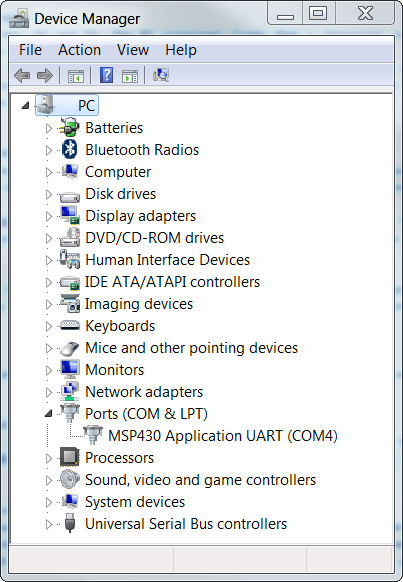
We know that the MSP430 UART is connected to COM Port 4. Open Putty and select serial mode.
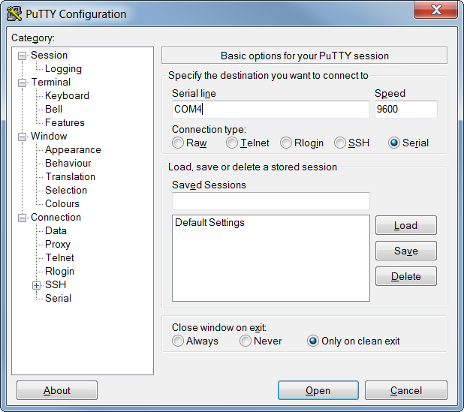
If putty opens up, you can begin typing and characters will be sent back to you.
Some systems attempt to transmit as much information as possible by using flow control. Two devices implementing flow control use two extra lines called Clear to Send(CTS) and Request to Send (RTS). The usage of these lines has varied, but at its core the MSP430 UART does not support any flow control. However, it is possible to implement it using GPIOs and interrupts. For example, one can begin transmitting will begin transmission when the GPIO ISR has triggered. It’s important to make sure that the RTS and CTS lines are used with ports supporting interrupts, typically ports 1 and 2.
Enter your email address to subscribe to this blog and receive notifications of new posts by email.