Clocks are at the heart of synchronous digital systems and processors. CPUs require clocks to run to ensure the orderly fetching and execution of instructions. In PCs, the selection of clock speeds is determined by various factors. Unless you are overclocking, you will never deal with them directly. Microcontrollers, on the other hand, are usually very flexible with clocks and require that you to specify what clocks will be used and at what speeds. This means you have to understand your application and what clocks are needed to satisfy your requirements.
One of the most obvious effects of clocks is the speed at which the CPU is processing data. If the clock is slow, algorithms will take longer to complete and the application can violate timing requirements. Another good example is the timing required for UART. UART is covered in a later chapter, but being asynchronous means that the reliability of the data being transmitted depends on the input clock, as is the speed at which it transmits data. If the clock is unstable and the baudrate is inaccurate, errors will be detected at the receiver.
The MSP430 clock system is very flexible and is built both to enable a fast CPU while at the same time supporting slow clocks that allow low power. With low power being the cornerstone of the MSP430, reducing the frequency of the CPU is critical to reducing power consumption. The dynamic power consumption can be shown to be: 1/2 C*V^2*f where V is the voltage, C the switching capacitance and f is the frequency of the circuit. Reducing the voltage and frequency can provide tremendous reductions in power consumption which makes products last longer on batteries.
Clock Generation
As with any system, clock generation contains many tradeoffs between size, accuracy and cost. More expensive solutions typically tend to produce better and cleaner clock signals that have lower jitter and drift. In the MSP430, the two main clock generation mechanisms are internal RC type oscillators and internal oscillators using external crystals.
The MSP430 can contain several internal oscillators. Of particular note are the Digital Controlled Oscillator and the VLO low frequency oscillator. Both of these are based on an RC network. RC networks can be rather inaccurate in generating precise clocks, so TI has trimmed and calibrated them to reach close to 1% accuracy. These type of oscillators are heavily affected by temperature and cannot be always be used for interfaces requiring accurate timing such as UART without causing errors. The DCO is digitally controlled because its frequency be changed from several hundred kHz up to 25MHz.
The MSP430 can also use external crystals with internal oscillator circuitry to generate both low frequency (32kHz) and high frequency (Up to 25MHz) clocks that are as accurate as the crystal used. One issue with crystals is that they are not tunable, so the only possible option is to divide them, but they are far more accurate, reaching 50ppm accuracy or better. A downside of using crystals is that they occupy more space on the board and increase the BOM cost, but when doing UART or needing accurate timing measurement they are practically obligatory.
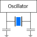
Crystals are accurate and they have low error due to aging. In general, every crystal is used in a parallel configuration, which is the case in the MSP430 and many other microcontrollers,. This requires capacitors to provide the load capacitance needed for the oscillator to oscillate at the right frequency. These capacitors are usually connected to the two crystal pins as shown in the figure above. The effective loading required is specified by the crystal manufacturer, not by the microcontroller manufacturer (although the microcontroller manufacturer could make recommendations or force you to use a certain loading because of built in capacitors). Any change in the effective loading changes the crystal’s effective frequency, which is an error in itself. However, it isn’t only the capacitors that add capacitance. The pins of the microcontroller as well as traces between the microcontroller and the crystal and the internal circuitry of the MSP430 oscillator also act as capacitors. To have an accurate frequency, a designer needs to take all of these elements into account. We will go through a simple exercise to demonstrate how to calculate the capacitors we should use.
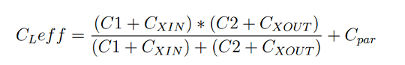
Let’s assume we need a 4MHz crystal and have selected one with 7pF of loading capacitance. C1 and C2, the loading capacitors, are usually selected to be the same, so we have:

Because both capacitors are the same, C1 = C2, we get 14pF of capacitance. Therefore, two capacitors of 14pF will provide us with the required load. This is quite simplistic and doesn’t take into account the other parasitics. The oscillator inside the microcontroller introduces two capacitances generally called CXIN and CXOUT. Each appears in parallel with one of the external loading capacitors. In addition to this, we also have the parasitics due to the PCB itself which are in parallel to the other capacitances.
Cpar is not always easy to measure. Because of this we typically assume a value of 2-5pF which works in most cases.
In some cases, external loading capacitors are actually not required. In the MSP430, several devices incorporate internal loading capacitors for the Low Frequency 32kHz watch crystals. The MSP430G2553 has 4 options for integrated effective load capacitance for low frequencies. You can choose between 1pF, 5.5pF, 8.5pF and 11pF, and these values also include the parasitic bond and package capacitance, which are around 2pF per pin. Note that you can still integrate external capacitors to try and compensate for parasitics, but this often causes more problems because the capacitors themselves have parasitics.
Whether you are using the integrated oscillators or external crystals, it is possible and advisable to measure the output frequency after a buffer. The MSP430 enables several clock sources to be output to a pin so the frequency can be measure using an oscilloscope or more accurately frequency counter.
We have discussed the clocks available, but typically they fall into the following:
- LFXT1CLK – Low frequency mode of the XT1 oscillator, typically used with watch crystals or clocks of 32.768kHz.
- HFXT1 – High frequency mode of the XT1 oscillator, used with High Frequency crystals. Not available in all MSP430 (not present in G2553 device)
- VLOCLK – Internal low frequency and low accuracy oscillator for low power
- DCOCLK – Internal Digitally Controlled Oscillator capable of generating a wide array of frequencies.
- XT2CLK – Optional high-frequency oscillator that uses standard crystals, resonators or external clocks in the 400kHz to 16MHz range or more.
- PxIN – If the pin is set to operate as GPIO Input, this pin indicates whether the voltage at the pin is High(0) or Low(0)
The exact clocks available on an MSP430 varies from device to device and between families. The datasheet and the User’s Guide are the best sources to see what is available the frequency information as well as accuracy specifications.
Clock Tree Signals
The clock tree in the MSP430 is actually composed of several signals whose source is selectable. This flexibility helps power CPU and peripherals using different clocks to achieve either speed or low power. The main signals in the MSP430 include:
- ACLK: Auxiliary clock. ACLK is software selectable as LFXT1CLK or VLOCLK. ACLK is divided by 1, 2, 4, or 8. ACLK is software selectable for individual peripheral modules.
- MCLK: Master clock. MCLK is software selectable as LFXT1CLK, VLOCLK, XT2CLK (if available on-chip), or DCOCLK. MCLK is divided by 1, 2, 4, or 8. MCLK is used by the CPU and system.
- SMCLK: Sub-main clock. SMCLK is software selectable as LFXT1CLK, VLOCLK, XT2CLK (if available on-chip), or DCOCLK. SMCLK is divided by 1, 2, 4, or 8. SMCLK is software selectable for individual peripheral modules.
The CPU of the MSP430 runs only from MCLK, while other peripheral modules can be sourced by any of the clock signals or in some cases from other clock sources brought in on specific pins.
Clocks on the MSP430 Launchpad
The Launchpad typically uses a MSP430G2553 device that contains a Basic Clock Module+. Only XT2 is unavailable on the device due to the lack of pins. XT1 supports both low frequency and high frequency crystals, and it integrates both DCOCLK and VLOCLK. After power-up, MCLK and SMCLK are sourced from DCOCLK at about 1.1MHz. ACLK is sourced from LFXT1CLK in LF mode. The Launchpad comes with an option 32kHz crystal in the box that needs to be installed by the user.
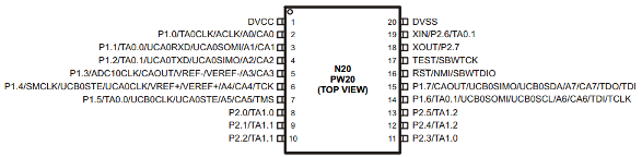
Pin 18 and Pin 19 are XIN and XOUT and allow an external crystal to be connected, either 32kHz or a fast crystal. Given the small number of pins, this is all that’s available on this device.
Internal DCO
Upon reset, the MSP430 does not know whether any external crystals are available, and what they are, so it defaults to using the internal DCO to power MCLK and other clocks. We mentioned before that the MSP430 will start up around 1.2MHz for the G2553. Let’s see how we can change the frequency to speed up the MSP430. TI has taken each MSP430 and performed a calibration of the DCO versus a known input frequency for several common frequencies. These calibration values provide DCO steps that result in a clock value as clock as possible to the frequency. The values themselves have been stored by TI on the Info flash segment, and care should be taken not to erase this segment of the flash.
Checking for DCO Calibration values in Flash
#include <msp430.h>
void main()
{
    WDTCTL = WDTPW + WDTHOLD; // Stop watchdog timer

    /* Check if 1MHz Calibration is present */
    if (CALBC1_1MHZ != 0xFF)
    {
        DCOCTL = 0; // Select lowest DCOx and MODx
        BCSCTL1 = CALBC1_1MHZ; // Set range
        DCOCTL = CALDCO_1MHZ; // Set DCO step + modulation
    }

    /* Check if 8MHz Calibration is present */
    if (CALBC1_8MHZ != 0xFF)
    {
        DCOCTL = 0; // Select lowest DCOx and MODx
        BCSCTL1 = CALBC1_8MHZ; // Set range
        DCOCTL = CALDCO_8MHZ; // Set DCO step + modulation
    }

    /* Check if 12MHz Calibration is present */
    if (CALBC1_12MHZ != 0xFF)
    {
        DCOCTL = 0; // Select lowest DCOx and MODx
        BCSCTL1 = CALBC1_12MHZ; // Set range
        DCOCTL = CALDCO_12MHZ; // Set DCO step + modulation
    }

    /* Check if 16MHz Calibration is present */
    if (CALBC1_16MHZ != 0xFF)
    {
        DCOCTL = 0; // Select lowest DCOx and MODx
        BCSCTL1 = CALBC1_16MHZ; // Set range
        DCOCTL = CALDCO_16MHZ; // Set DCO step + modulation
    }
}
The code above is more of an example than real code. It goes through every DCO calibration setting and actually sets the DCO to that value. Typically you would just pick one value to run or have a more sophisticated approach. It’s very important that you check whether the calibration value is valid. If the Info flash with the values was erased, its value would be 0xFF. Let’s try out the speed of the DCO. The code below will blink the LED of the Launchpad using the default DCO speed, and then using the DCO at 16MHz to show that the speed is actually changing, and what the effect is.
Configuring MSP430 DCO to 8MHz
void main()
{
    WDTCTL = WDTPW + WDTHOLD; // Stop watchdog timer
    P1SEL &= (~BIT0);
    P1OUT &= (~BIT0);
    P1DIR |= (BIT0);

    for(blink_count = 0; blink_count < 10; blink_count++)
    {
        P1OUT ^= (BIT0); // Toggle LED
        for(i = 0; i < 20000; i++);
    }

    /* Check if 8MHz Calibration is present */
    if (CALBC1_8MHZ != 0xFF)
    {
        DCOCTL = 0; // Select lowest DCOx and MODx
        BCSCTL1 = CALBC1_8MHZ; // Set range
        DCOCTL = CALDCO_8MHZ; // Set DCO step + modulation
    }

    for(blink_count = 0; blink_count < 10; blink_count++)
    {
        P1OUT ^= (BIT0); // Toggle LED
        for(i = 0; i < 20000; i++);
    }
}
After blinking a few times slowly, the LED will blink rapidly and then turn off.
External 32kHz Clock
The following code makes P2.6 and P2.7 set for accepting a crystal at the input:
MSP430 Using External 32kHz crystal
#include <msp430.h>
void main()
{
    WDTCTL = WDTPW + WDTHOLD; // Stop watchdog timer
    P2SEL |= (BIT6 | BIT7); // Set P2.6 and P2.6 SEL for XIN, XOUT
    P2SEL2 &= ~(BIT6|BIT7); // Set P2.6 and P2.7 SEL2 for XIN, XOUT

    /* Select 32kHz Crystal for ACLK */
    BCSCTL1 &= (~XTS); // ACLK = LFXT1CLK
    BCSCTL3 &= ~(BIT4|BIT5); // 32768Hz crystal on LFXT1

    /* Output buffered ACLK on P1.0 */
    P1SEL |= BIT0;
    P1SEL2 &= ~(BIT0);
    P1DIR |= BIT0;
}
If you have installed the 32kHz crystal that comes with the MSP430 Launchpad, you will see the following output as measured on P1.0. Make sure to remove the Jumpers for the LEDs because the presence of an LED on P1.0 will create problems with the output of ACLK.